Home EEE Projets Robotic Projects ECE Projects


Control stepping motor via USB interface


This is an example that demonstration how to control some devices via USB interface.The PC software program with windows..


Feature :
- CPU PIC18F4550 with full speed USB interface at 48MHz.
- USB 2.0 compliance
- Use on-chip USB driver
- Control 1 stepping motor.
- CCS/MikroC firmware at USB devices side.
- VC++/VB for PC Host software.


USB devices side

Figure 1. is the schematic for this example.PIC18F4550 is the main devices that communicate with PC and control stepping motor. The power supply came from +5V Vbus for circuit except +Vmotor which must use external power supply that depend on stepping motor requires. If you add more components into circuit that drawn total current more than 250mA you should be use +5V external power supply instead Vbus.Becuase Vbus can supplies current not more than 250mA and don't forgot to disconnect Vbus out of circuit.


In this example I drive the stepping motor with 1-phase drive method(A-C-B-D).You may be change for your appropriate application.


Figure 1. Schematic for this example


Firmware


The firmware for this example program with CCS/MikroC with USB driver from Microchip.
PC software side

This example program with windows VC++/VB which modified from C++ wrote by Microchip staff. I have modified the original source code for 3 command for this example : turn left,turn right,Stop motor and connect.For detail of C++ example see in PICDEM™ FS USB User’s Guide and relate files.


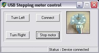
The USB driver which use for this project is the Microchip General Purpose USB Windows driver which programming with C/C++ .If you need to program your own USB driver look at this website which have more interest USB driver programming information(www.jungo.com). But, programming USB driver is so hard works.Also,you need to know how dose the OS work.

for more infomation about USB please go to :
http://www.usb.org
http://www.microchip.com